


Service Hotline

Products
Products
Products
MengziDY Electro-Hydraulic Coupling Device
Category:
MengziHydraulic transmission device
MengziNew DY Electro-hydraulic Drive
Product Description
- [Abstract] This article introduces the technology and application examples of speed-regulating hydrodynamic transmissions and electro-hydrodynamic drive systems, while also comparing them with mainstream conventional variable-frequency soft-start technologies. Electro-hydrodynamic transmission and drive technology is a new type of drive system that was introduced from Germany after 2010, incorporating and adapting advanced technologies. However, due to its relatively short time in market promotion, there remains limited design and operational experience in this field.
【 Keywords 】 Soft start, stepless speed regulation, flexible coupling, clutch function, torque limitation, overload protection, and damping.
Preface
Since the 1980s, requirements for energy conservation, consumption reduction, and emission reduction have been placed on the agenda. To achieve these goals, methods such as adjusting motor frequency, voltage, and speed, as well as employing hydrodynamic transmission to modify the operating machinery's rotational speed, have been utilized in pursuit of energy-saving and emission-reducing outcomes. Electrical control methods include cascade-controlled silicon-controlled rectifiers, wound-rotor motors like DC motors and variable-frequency motors, which use inverters to regulate motor speed. Mechanical transmission methods encompass the YOTC series of speed-regulating hydraulic couplings, hydroviscous speed regulators, CST soft starters, and magnetic couplings.I. YOTC Series Speed-Regulating Hydraulic Couplings
After extensive comparative use, the YOTC series of variable-speed hydraulic couplings have been widely recognized as an ideal solution for addressing soft starting, power balancing, and energy-saving requirements in equipment applications. Since their introduction onto the energy-saving stage in the 1980s, these variable-speed hydraulic couplings have steadily gained prominence over the past three decades. On average, approximately 3,000 units are introduced annually to the market, serving mechanical equipment across industries such as power generation, steel production, coal mining, chemical processing, building materials, port operations, and transportation. As a result, they have significantly enhanced operational efficiency and contributed substantially to energy conservation efforts in these critical sectors.Principle of Operation for the YOTC Series Speed-Regulating Hydraulic Couplings
● The power transmission method of the YOTC coupler
The prime mover drives the oil pump to rotate, causing the working fluid to be pumped into the coupling's working chamber. The pump impeller, functioning like a centrifugal pump, imparts kinetic and potential energy to the oil within the working chamber. As the oil rushes outward from the inner rim of the impeller toward its outer edge, it flows through the gap between the two wheels and reaches the turbine. Here, the turbine acts as a turbomachinery component: as the fluid stream moves radially inward through the channels formed by the turbine blades, the fluid's kinetic energy is converted into mechanical energy that drives the turbine. Upon returning to the pump impeller, the fluid initiates the next cycle. In this way, the continuously circulating fluid transmits the motor's power to the driven machine.
● The speed control method of YOTC hydraulic couplings
When the equipment is started, the oil pump driven by the gear on the input shaft pumps out the oil from the bottom of the coupling housing. The oil then flows through the water-cooled oil cooler and is injected into the working chamber via the inlet port.
When the coupling is operating, the hydraulic fluid overflows from the working chamber through channels along the outer edge of the turbine and enters the guide tube cavity. Inside the guide tube housing, there is a horizontally positioned guide tube that can extend radially in and out. (Refer to the accompanying figure for details.) The tip of the guide tube extends into the guide tube cavity, and its extension or retraction is controlled by an external electric actuator. The radial position of the guide tube's tip directly determines the thickness of the oil ring within the guide tube cavity, which in turn regulates the amount of fluid filling the working chamber—and thus controls the output rotational speed. When the guide tube extends into the rotating oil ring, it draws oil out of the guide tube cavity, reducing the thickness of the oil ring. This action removes fluid from the working chamber and directs it toward the bottom of the housing, where it is collected for recirculation. Conversely, when the guide tube retracts, it increases the thickness of the oil ring, allowing more fluid to remain in the working chamber. By using an external control mechanism to adjust the guide tube cavity between these two extreme positions—“full” and “empty”—the system achieves stepless speed variation of the output shaft. It is important to note that the tip of the guide tube must face the direction of rotation of the working oil. YOT C Structure Schematic Diagram (with Illustration)Advantages of the YOTC Series Speed-Regulating Hydraulic Couplings:
1. Enhance the starting capability of squirrel-cage motors by leveraging the motor's peak torque as the starting torque, enabling compatibility with high-voltage motors.
2. Prevent power overload and protect the motor and working machinery from damage caused by excessive load.
3. Reduce vibrations and shocks during startup, enabling smooth motor start-up.
4. The drive system enables power balancing and sequential starting, reducing the inrush current impact on the power grid.
5. The startup time of the working machine can be safely configured according to operational requirements.
6. The working machine features stepless speed regulation with high precision (1%), delivering remarkable energy-saving benefits, achieving an energy-saving rate of 20% to 40%.
7. The work machine supports manual control, remote control, and automated operation, making it highly convenient to operate.
8. Insensitive to ambient temperature, with easy heat dissipation.
9. Simple in structure and highly reliable, it offers a lower price and reduced operating costs compared to variable-frequency drives and CST speed controllers. Additionally, it features no mechanical wear, can operate effectively under harsh environmental conditions, requires minimal specialized maintenance, and boasts an exceptionally long service life.

II. Upgraded Electromechanical Integration Drive Technology Featuring Computer Control and Variable-Speed Hydraulic Couplings (DYC, DY)
In high-power speed control applications and equipment requiring soft starting under heavy loads, the use of speed-regulating hydraulic couplings as transmission devices is an excellent choice. Firstly, they are widely favored for their reliability, durability, and cost-effectiveness. However, due to the inherent nonlinear characteristics of hydraulic couplings themselves, it becomes increasingly challenging to meet the stringent demands for improved speed control performance in modern industrial settings. Secondly, many of the applications involving hydraulic couplings are found in large-scale industrial and mining enterprises that have achieved a high degree of automation. These enterprises not only demand ever-higher standards for product quality and performance but also place significant emphasis on electrical integration, automation, and advanced process control. As a purely mechanical end-product, the hydraulic coupling alone cannot satisfy these sophisticated requirements, thereby hindering its broader adoption in such industries.
Currently, the hydraulic coupling control cabinets used in the market primarily rely on conventional, general-purpose instruments to manage and monitor the operation of the hydraulic couplings. However, these control cabinets are overly simplistic, with their electrical components merely serving passively to support the operation of the hydraulic couplings—without being integrally linked to them. As a result, they fail to play a critical role in optimizing the speed regulation performance.
To achieve this, the concept of electro-hydrodynamic (D&Y) electromechanical integration is employed. Leveraging today's advanced microcomputer technology, a dedicated intelligent control system has been developed and seamlessly integrated with the speed-regulating hydraulic coupling, creating a more efficient transmission and speed-control mechanism: the electro-hydrodynamic drive unit. This innovative system represents an organic combination of a specialized speed-regulating hydraulic coupling and a tailored intelligent control device. It not only retains the excellent transmission characteristics inherent to the hydraulic coupling but also endows the equipment with intelligent features, making it easier to operate and control effectively.
The output speed of the electro-hydraulic transmission equipment maintains a nearly linear relationship with the given command, enabling stepless speed regulation. This system not only addresses the nonlinearity issues inherent in hydraulic coupling control but also leverages the advantages of high transmission power, low cost, and simple maintenance and operation. Additionally, it ensures that all auxiliary systems of the electro-hydraulic transmission equipment can automatically start or stop according to process requirements, supporting both local and centralized remote control operations.
(1) Adhering to the principle of integrating mechanical and electrical technologies, we have seamlessly combined modern computer technology with traditional hydraulic couplings, introducing the concept of electro-hydraulic transmission equipment. This innovative approach effectively meets the demands for soft starting and stepless speed regulation in high-power applications. For instance, it is ideally suited for applications such as variable-speed soft starters used in high-power fans, pumps, elevators, coal crushers, mining machinery, and belt conveyors. Additionally, in scenarios involving multiple drives under heavy-load conditions, this system can be conveniently integrated into a synchronized multi-drive control system, exemplified by the Belt Conveyor Drive Control (DYC) unit designed for multi-motor drive configurations in belt conveyors.
(2) At the core of the electro-hydraulic transmission equipment control system is an intelligent controller programmed in C language. Specifically designed to address the unique characteristics of fluid couplings, this controller integrates artificial intelligence with a fuzzy control algorithm that combines PID and AI techniques, enabling effective and precise control of the fluid coupling. All control functions are consolidated within a universal housing unit, offering intuitive operation that is both concise and highly practical. Additionally, in applications requiring advanced automation, the system can easily be networked for remote monitoring and control.


On-site Universal Box Touchscreen Display Interface Remote Computer Configuration Software Interface
• The innovative DYC electro-hydraulic flexible transmission and drive technology was introduced from Germany at the end of the last century. After nearly 20 years of absorption and transformation, it has evolved into a versatile technology applicable to the next-generation mechanical transmission and drive systems.
• Equipped with five major functions: Clutch, flexible coupling, soft start, stepless speed regulation, overload protection ;
• Capable of providing a one-stop solution to critical issues in mechanical transmission & drive systems: Overload soft start, dynamic load hazards, torque limitation, stepless speed regulation ;
• Compared to traditional mechanical transmission & drive technologies, it improves efficiency by more than 30% (reducing energy consumption, lowering costs, and minimizing emissions).
• It is a more straightforward, cost-effective, and user-friendly mechatronic integration technology.
Has been successfully used for:
• Diesel-electro-hydraulic drive system for chain bucket dredgers (Soft start, stepless speed regulation)
• The drive system employs a diesel engine combined with DY electro-hydraulic power transmission and a gearbox (similar to the drive mechanism used in coal-carrying belt conveyors).
• The rotational speed is reduced from 1200 rpm to 4 rpm via a diesel engine, passing through Gearbox #1, a belt-pulley assembly, Gearbox #2, and finally a chain-driven bucket. This represents a typical hybrid mechanical drive system incorporating belt, chain, and gear transmissions. The bucket extracts sand at a frequency of 8–10 inches per cycle, resulting in high fluctuation density and significant impact in dynamic loads. Consequently, the alternating torsional vibrations generate extremely severe issues. However, the adoption of a novel electro-hydraulic drive technology has successfully addressed these challenges. Belt slippage, gear wear, spindle fracture, and black smoke from the diesel engine The issue demonstrates significant energy-saving effects.• Applications of Multi-Point Drive Control (Hongguo Coal Transfer and Loading Station, Liupanshui, Guizhou)
• 8 00kW × 2 Belt Conveyor DY Electro-Hydraulic Dual-Drive Intelligent Dynamic Control System
• Features: Soft start, multi-drive power balancing, stepless speed regulation, flexible coupling, clutch mechanism, and overload protection• High-power pump配套 (vertical pump, horizontal pump)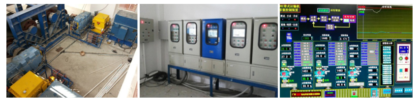
• Speed Control and Energy Saving System
• Laigang Wide and Thick Plate Plant
• 750 kW pump• Formosa Ha Tinh Steel Plant's 2,800 kW Dust Removal Fan (750 rpm)
• Soft Start, Speed Control, and Energy-Saving System Unified• Can be used for tube mills, vertical mills, and rotary kilns.
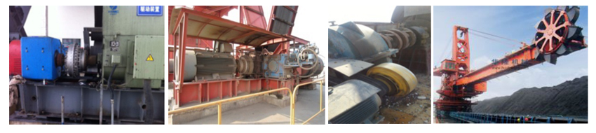
• Equipped with functions such as clutch operation, soft start, flexible coupling, stepless speed regulation, overload protection, and damping.• Widely applied across a diverse range of mechanical equipment...

III. Upgraded Version of Computer-Controlled and Speed-Regulating Hydraulic Coupling (DYC, DY) – Electromechanical Integrated Drive Technology
Project/Product Hydrodynamic Speed Control Soft Start Variable-frequency speed control soft start 1. Performance 1. Adjust the fluid charge to achieve stepless speed regulation of the working mechanism.
2. Perform a soft start for the system, which can take an extended period of time without any limitations on the number of starts.
3. High overload capacity, capable of utilizing the motor's peak torque, with strong heavy-load starting capability.
4. Multi-machine drive enables power balancing and features automatic control of speed and current.1. Adjust the motor frequency for stepless speed control of the motor.
2. Perform a soft start for the system, which may take an extended period of time.
3. Poor overload capacity—increasing the overload factor requires upgrading the frequency converter to a higher level, which would add several hundred thousand yuan in cost per upgrade level.
4. Adjusting the motor frequency enables power balancing.2. Price Low investment Overall investment is high (requiring dedicated air-conditioned, ventilated, and dust-free electrical rooms as well). 3. Reliability High reliability
1. Even if the control system fails, the device can still be operated manually.
2. Simple structure, eliminating the need for a bypass system.Low reliability
1. If any component in the complex control system of the frequency converter fails, the system will become inoperable.
2. The structure is complex, and reliability decreases further in high-altitude areas. Although the electrical components used in current variable frequency drives have improved in reliability compared to earlier models, the large number of components—often numbering in the thousands—in a typical large-scale VFD significantly reduces overall system reliability. Therefore, for critical applications, it is essential to have either a speed-adjustable or fixed-speed bypass control system as a backup.4. Power Supply Fluctuation Voltage fluctuations do not affect the operation of the coupler. When the supply voltage drops below 80% of its rated value due to various reasons, the electronic inverter's built-in protection mechanism will automatically cut off the motor power supply. Even if the voltage drop lasts for just 100 microseconds, the protection system will activate immediately. The electronic inverter can be equipped with an automatic restart feature (which requires additional investment). 。
Even so, it takes at least 5 to 10 seconds for the motor to restart. During this period, the motor will come to a complete stop due to power failure, potentially causing significant disturbances to the process system and even triggering a safety shutdown of the plant. In smaller power supply systems, voltage dips are particularly prone to occur.
5. Harmonic Impact No harmonic interference Electronic variable-frequency drives generate higher-order harmonics of current and voltage in the power supply system. The magnitude of these harmonics depends on the size of the drive, the specific type of inverter used, as well as the short-circuit capacity of the power supply system. In systems with low power supply capability—particularly those characterized by smaller electrical capacities—the harmonic interference becomes especially pronounced. Such interference includes:
● Additional losses are generated in the motor and power supply transformer (therefore, the motor must be selected slightly larger, typically by about 12%).
● Motors and transformers generate additional noise (2–5 dB[A]).
● In addition to generating normal driving torque, the motor will produce pulse torque (these torsional vibrations will also be transmitted to the working machine, increasing mechanical impact and energy loss).
● Harmonic interference leads to additional energy consumption losses throughout the power supply system.
● Causes adverse effects on other electrical equipment and personnel, such as computers, controllers, etc.
● Harmonic issues may arise in capacitor banks, voltage transformers, ballasts, or capacitors within the power supply system, leading to increased energy consumption.
● May require the installation of harmonic filters to mitigate the effects of harmonics (which will incur additional investment and maintenance costs).6. Power Factor
Efficiency
High power factor with an efficiency of 97–98%.
Low power factor and low efficiency—typically ranging only from 90% to 94%—often mislead users regarding the true performance of variable frequency drives. First, accurately determining their efficiency through load testing is both challenging and extremely costly. Second, the additional losses caused by harmonics in motors, transformers, and the entire system are frequently overlooked. Lastly, the energy consumption associated with air conditioning cooling systems and harmonic filters is also typically not factored into the efficiency calculations.
Efficiency of the inverter at different speeds: (Siemens-produced Robicon Perfect Harmony series inverter)
Inverter efficiency %
Rotational Speed %
20
40
60
80
100
Torque %
20
74.6–85.9
84.9–94.8
89.2–94.2
91.5–95.3
92.8–96
40
84.5 to 91.0
91–95.5
93.2–96.1
94.8–96.6
95.6–96.9
60
88.3–92.5
93.2–95.7
95 to 96.4
95.9–96.8
96.3–97
80
93 to 90.3
94.3–95.7
95.7–96.4
96.2–96.9
96.6–96.8
100
91.4–93.2
94.8–96.7
95.9 to 95.7
96.4–96.5
96.5–96.6
7. Matching Motors
Standard squirrel-cage induction motor
It must use a dedicated variable-frequency motor, whose rated current is 8–10% higher than that of a standard induction motor, resulting in a 20% increase in temperature rise.
8. Voltage Transformation Requirements
Available high-pressure and low-pressure electric motors
If a low-voltage electronic frequency converter is used (since medium- and high-voltage converters are expensive and have lower reliability), a special step-down transformer must be employed, which inevitably leads to additional investment, increased floor space requirements, and higher maintenance demands. Alternatively, if a high-voltage motor is utilized—typically paired with a low-voltage frequency converter—a dedicated step-up transformer must be installed between the converter's output and the speed-controlled motor. This transformer must be rated for substantial capacity, as it needs to operate at frequencies below 50 Hz while preventing magnetic saturation during low-frequency startup.
9. Land Area
Smaller
The electrical switch room for high-power inverters requires significant space, leading to increased investment costs.
10. Electrical Cabinet Cooling System
No additional cooling required.
The heat loss generated within the inverter enclosure must be dissipated. This heat loss accounts for approximately 5% of the rated power, independent of the actual motor load and speed. For high-power inverters, this loss becomes particularly significant. The cooling air must be filtered through a dedicated cooling fan before being blown into the enclosure to maintain a cool operating environment. The maximum allowable temperature of the cooling air is 40°C, which necessitates substantial air circulation. As a result, the energy consumption associated with air conditioning and cooling fans often exceeds the inverter's own power losses.
Additionally, an air-to-water heat exchanger can also be used; however, this option involves high initial investment and significant maintenance costs.
11. Electrical Cabinet Noise
None
The inverter generates significant noise. Large-scale inverters produce noise levels exceeding 85 dB(A).
12. Equipment Maintenance
General Mechanical Maintenance
Troubleshooting and maintenance are highly time-consuming and costly; therefore, to resolve the issue, it is essential to consult with experts from the supplier.
13. Spare Parts
Affordable mechanical spare parts
A large number of spare parts are required, and only the manufacturer can supply them. However, due to the rapid advancements and changes in electronic technology, some components will become obsolete within just a few years, making it increasingly difficult to procure them.
14. Packaging and Transportation
Standard Equipment Packaging
The costs associated with factory testing, packaging, transportation, installation, and equipment startup are extremely high. Typically, these expenses are not factored into the comparison of equipment prices—nor are the costs for training maintenance personnel and organizing product documentation.
15. Additional Cables
No need.
If low-voltage motors are used in conjunction with low-voltage variable frequency drives, the connecting cables between the step-down transformer and the input terminals of the VFD, as well as those between the VFD output terminals and the speed-regulating motor, must be connected in parallel using multiple cables (e.g., four cables are required for a rated current of 1000 A). Additionally, these cables should be terminated in a dedicated junction box specifically designed for motor wiring. During motor maintenance, all such connections must be disconnected, a task that can be challenging due to the large diameter of the cables. Furthermore, the significant heat loss within these thick cables can substantially impact overall system efficiency.
16. Lubrication System
The hydraulic coupling is equipped with a lubrication system that provides lubricating oil to the bearings of both the motor and the working machine.
Large high-speed motors typically use sliding bearings instead of rolling bearings. Motor sliding bearings, as well as pump bearings, require regular maintenance. These sliding bearings must be supplied with oil for lubrication, necessitating the installation of a separate lubrication system—adding both additional costs and maintenance requirements.
17. Frequency Conversion Method
There is no such requirement.
There are essentially two types of inverters: voltage-source inverters and current-source inverters. Voltage-source inverters have lower efficiency and generate more higher-order harmonics compared to current-source inverters. If no motor is connected at the output end of a current-source inverter, the inverter will be running under no-load conditions. Under such circumstances, neither operation nor trial runs can be performed, nor can faults be tested or diagnosed, as these tasks cannot be carried out when the system is unloaded. If a motor is not available at that moment, or if the motor has not yet been prepared, or if operational constraints due to factory conditions prevent its activation, these limitations can lead to significant inconvenience.
18. Control System
Adopt a simple on-site control system. Equipped with on-site/remote/automatic/manual modes.
The frequency converter requires the arrangement of additional control and monitoring equipment in the switchgear room where the converter is installed. This means that extra cables, relays, internal interlocking systems, and starting circuit devices must be added to meet the control requirements, thereby increasing costs, failure rates, and maintenance workload.
19. Explosion-proof Requirements
Speed-regulating hydraulic couplings all come with underground safety certification.
Meeting explosion-proof requirements involves significant cost expenditures and is relatively difficult to achieve.
From the comparison above, it is evident that both hydraulic speed control soft starters and variable-frequency drive soft starters can achieve soft starting and multi-drive power balancing. However, as shown in the comparisons from point 2 to point 19, the use of a variable-frequency drive system is more complex, involves additional drawbacks, has a shorter service life, and incurs higher management and operational costs.
IV. Energy Efficiency Comparison Between Variable Frequency Soft Start and Hydraulic Soft Start
DY Electro-Hydraulic Energy-Saving Drive System, featuring a rated transmission efficiency of 97–98.5%, with no electromagnetic or electrostatic interference. It operates on standard power frequency and is designed to work seamlessly with asynchronous energy-saving motors, forming an ultra-high-efficiency drive system that delivers even greater energy savings. Variable-frequency speed control utilizes a variable-frequency motor, which, at rated operation, draws 8–10% higher current and experiences a temperature rise that is 20% greater compared to standard asynchronous motors. Additionally, the heat generated by the inverter itself amounts to 50–60 watts per 1 kVA of capacity, resulting in additional energy consumption when compared to using a power supply operating at line frequency. Additionally, to enhance the reliability and stability of inverter operation, extensive auxiliary peripheral electrical equipment must also be configured, including transformers, power circuit breakers, AC contactors, filters, reactors, braking resistors, and more. These electrical configurations collectively account for a power consumption exceeding 5%. It is evident that, compared to the DY electro-hydraulic energy-saving drive system, the variable-frequency drive system exhibits higher overall energy consumption and lower efficiency under rated operating conditions.
V. The DY electro-hydraulic drive unit also features excellent flexible transmission characteristics.
DY electro-hydraulic flexible transmission and drive technology not only delivers excellent drive control performance but also leverages the unique advantages of hydraulic flexible transmission. By optimizing the start-up and operational characteristics of working machinery, it effectively mitigates the hazards associated with dynamic loads (such as torsional vibration, resonance, and overload), thereby reducing operational maintenance costs. Additionally, this technology helps minimize configuration redundancy in transmission and drive systems, ultimately lowering overall investment expenses.
1. By altering the resonant speed of the shaft system, a larger torsional angle based on torque (indicating lower stiffness) results in smaller impact torque and a lower resonant speed. The torsional stiffness of the hydraulic coupling device is adjustable, allowing it to operate at an optimal torsional angle (slip) according to the varying load torque, thereby minimizing resonance.
2. Reduces torsional vibrations in the shaft system, making it particularly suitable for operating conditions with frequent load fluctuations. The hydraulic coupling device uses 30–40# turbine oil as the transmission medium, providing significant viscous damping (increasing frictional resistance). Capable of rapidly attenuating vibrations, converting the energy of torsional oscillations into heat, and dissipating it through thermal radiation. This will help reduce mechanical impact and wear in the transmission shaft system, enhancing reliability and extending service life.
3. When equipment operation is subjected to unexpected overloads, it often leads to damage of the transmission system or other mechanical components. If a hydraulic coupling device is employed in the drive shaft system, Leverage its clutch (semi-clutch) function By interrupting the transmission torque or limiting torque transfer, a safety protection function can be achieved.
4. The DY electro-hydraulic drive features a clutch function, enabling the motor and working machine to start independently. This clutch characteristic ensures that the motor can initiate operation either under no-load or heavy-load conditions—allowing for full-voltage starting of the motor. As a result, startup time is significantly reduced, and inrush current is minimized, eliminating the need to address the common issue of "using an oversized motor for light-duty applications." The motor starts first; once it reaches its rated speed, the hydraulic coupling is gradually engaged to smoothly load the working machine, achieving stepless speed control from 0% to 100%. Traditional variable-frequency control relies on conventional V/f control, where the voltage drop across the motor increases relatively as the motor speed decreases. This, in turn, leads to insufficient excitation, causing the motor to fail to generate adequate rotational torque. Under heavy-load conditions, it becomes necessary to equip the motor with a margin exceeding 1.5 times its rated capacity; otherwise, the motor may lack sufficient power during startup.
Through the comprehensive comparison outlined above, the new DYC electro-hydraulic speed-regulating soft-start device technology can replace the currently conventional variable-frequency and CST drives. It offers superior performance, requires lower equipment investment costs, achieves higher operational efficiency, and incurs lower running and maintenance expenses—making it the more suitable and advanced technology for industrial machinery transmission and drive systems.New DY Electro-Hydraulic Speed Control Soft StarterA new technology for transmission & drive systems in high-power industrial machinery.
- [Abstract] This article introduces the technology and application examples of speed-regulating hydrodynamic transmissions and electro-hydrodynamic drive systems, while also comparing them with mainstream conventional variable-frequency soft-start technologies. Electro-hydrodynamic transmission and drive technology is a new type of drive system that was introduced from Germany after 2010, incorporating and adapting advanced technologies. However, due to its relatively short time in market promotion, there remains limited design and operational experience in this field.
【 Keywords 】 Soft start, stepless speed regulation, flexible coupling, clutch function, torque limitation, overload protection, and damping.
Preface
Since the 1980s, requirements for energy conservation, consumption reduction, and emission reduction have been placed on the agenda. To achieve these goals, methods such as adjusting motor frequency, voltage, and speed, as well as employing hydrodynamic transmission to modify the operating machinery's rotational speed, have been utilized in pursuit of energy-saving and emission-reducing outcomes. Electrical control methods include cascade-controlled silicon-controlled rectifiers, wound-rotor motors like DC motors and variable-frequency motors, which use inverters to regulate motor speed. Mechanical transmission methods encompass the YOTC series of speed-regulating hydraulic couplings, hydroviscous speed regulators, CST soft starters, and magnetic couplings.I. YOTC Series Speed-Regulating Hydraulic Couplings
After extensive comparative use, the YOTC series of variable-speed hydraulic couplings have been widely recognized as an ideal solution for addressing soft starting, power balancing, and energy-saving requirements in equipment applications. Since their introduction onto the energy-saving stage in the 1980s, these variable-speed hydraulic couplings have steadily gained prominence over the past three decades. On average, approximately 3,000 units are introduced annually to the market, serving mechanical equipment across industries such as power generation, steel production, coal mining, chemical processing, building materials, port operations, and transportation. As a result, they have significantly enhanced operational efficiency and contributed substantially to energy conservation efforts in these critical sectors.Principle of Operation for the YOTC Series Speed-Regulating Hydraulic Couplings
● The power transmission method of the YOTC coupler
The prime mover drives the oil pump to rotate, causing the working fluid to be pumped into the coupling's working chamber. The pump impeller, functioning like a centrifugal pump, imparts kinetic and potential energy to the oil within the working chamber. As the oil rushes outward from the inner rim of the impeller toward its outer edge, it flows through the gap between the two wheels and reaches the turbine. Here, the turbine acts as a turbomachinery component: as the fluid stream moves radially inward through the channels formed by the turbine blades, the fluid's kinetic energy is converted into mechanical energy that drives the turbine. Upon returning to the pump impeller, the fluid initiates the next cycle. In this way, the continuously circulating fluid transmits the motor's power to the driven machine.
● The speed control method of YOTC hydraulic couplings
When the equipment is started, the oil pump driven by the gear on the input shaft pumps out the oil from the bottom of the coupling housing. The oil then flows through the water-cooled oil cooler and is injected into the working chamber via the inlet port.
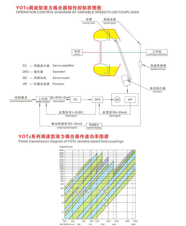
When the coupling is operating, the hydraulic fluid overflows from the working chamber through channels along the outer edge of the turbine and enters the guide tube cavity. Inside the guide tube housing, there is a horizontally positioned guide tube that can extend radially in and out. (Refer to the accompanying figure for details.) The tip of the guide tube extends into the guide tube cavity, and its extension or retraction is controlled by an external electric actuator. The radial position of the guide tube's tip directly determines the thickness of the oil ring within the guide tube cavity, which in turn regulates the amount of fluid filling the working chamber—and thus controls the output rotational speed. When the guide tube extends into the rotating oil ring, it draws oil out of the guide tube cavity, reducing the thickness of the oil ring. This action removes fluid from the working chamber and directs it toward the bottom of the housing, where it is collected for recirculation. Conversely, when the guide tube retracts, it increases the thickness of the oil ring, allowing more fluid to remain in the working chamber. By using an external control mechanism to adjust the guide tube cavity between these two extreme positions—“full” and “empty”—the system achieves stepless speed variation of the output shaft. It is important to note that the tip of the guide tube must face the direction of rotation of the working oil.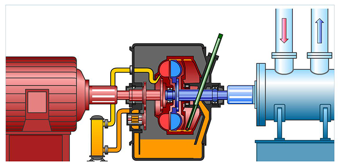 YOT C Structure Schematic Diagram (with Illustration)Advantages of the YOTC Series Speed-Regulating Hydraulic Couplings:
1. Enhance the starting capability of squirrel-cage motors by leveraging the motor's peak torque as the starting torque, enabling compatibility with high-voltage motors.
2. Prevent power overload and protect the motor and working machinery from damage caused by excessive load.
3. Reduce vibrations and shocks during startup, enabling smooth motor start-up.
4. The drive system enables power balancing and sequential starting, reducing the inrush current impact on the power grid.
5. The startup time of the working machine can be safely configured according to operational requirements.
6. The working machine features stepless speed regulation with high precision (1%), delivering remarkable energy-saving benefits, achieving an energy-saving rate of 20% to 40%.
7. The work machine supports manual control, remote control, and automated operation, making it highly convenient to operate.
8. Insensitive to ambient temperature, with easy heat dissipation.
9. Simple in structure and highly reliable, it offers a lower price and reduced operating costs compared to variable-frequency drives and CST speed controllers. Additionally, it features no mechanical wear, can operate effectively under harsh environmental conditions, requires minimal specialized maintenance, and boasts an exceptionally long service life.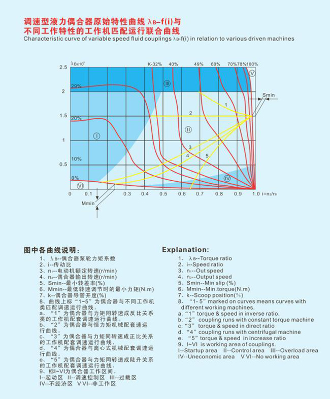
II. Upgraded Electromechanical Integration Drive Technology Featuring Computer Control and Variable-Speed Hydraulic Couplings (DYC, DY)
In high-power speed control applications and equipment requiring soft starting under heavy loads, the use of speed-regulating hydraulic couplings as transmission devices is an excellent choice. Firstly, they are widely favored for their reliability, durability, and cost-effectiveness. However, due to the inherent nonlinear characteristics of hydraulic couplings themselves, it becomes increasingly challenging to meet the stringent demands for improved speed control performance in modern industrial settings. Secondly, many of the applications involving hydraulic couplings are found in large-scale industrial and mining enterprises that have achieved a high degree of automation. These enterprises not only demand ever-higher standards for product quality and performance but also place significant emphasis on electrical integration, automation, and advanced process control. As a purely mechanical end-product, the hydraulic coupling alone cannot satisfy these sophisticated requirements, thereby hindering its broader adoption in such industries.
Currently, the hydraulic coupling control cabinets used in the market primarily rely on conventional, general-purpose instruments to manage and monitor the operation of the hydraulic couplings. However, these control cabinets are overly simplistic, with their electrical components merely serving passively to support the operation of the hydraulic couplings—without being integrally linked to them. As a result, they fail to play a critical role in optimizing the speed regulation performance.
To achieve this, the concept of electro-hydrodynamic (D&Y) electromechanical integration is employed. Leveraging today's advanced microcomputer technology, a dedicated intelligent control system has been developed and seamlessly integrated with the speed-regulating hydraulic coupling, creating a more efficient transmission and speed-control mechanism: the electro-hydrodynamic drive unit. This innovative system represents an organic combination of a specialized speed-regulating hydraulic coupling and a tailored intelligent control device. It not only retains the excellent transmission characteristics inherent to the hydraulic coupling but also endows the equipment with intelligent features, making it easier to operate and control effectively.
The output speed of the electro-hydraulic transmission equipment maintains a nearly linear relationship with the given command, enabling stepless speed regulation. This system not only addresses the nonlinearity issues inherent in hydraulic coupling control but also leverages the advantages of high transmission power, low cost, and simple maintenance and operation. Additionally, it ensures that all auxiliary systems of the electro-hydraulic transmission equipment can automatically start or stop according to process requirements, supporting both local and centralized remote control operations.
(1) Adhering to the principle of integrating mechanical and electrical technologies, we have seamlessly combined modern computer technology with traditional hydraulic couplings, introducing the concept of electro-hydraulic transmission equipment. This innovative approach effectively meets the demands for soft starting and stepless speed regulation in high-power applications. For instance, it is ideally suited for applications such as variable-speed soft starters used in high-power fans, pumps, elevators, coal crushers, mining machinery, and belt conveyors. Additionally, in scenarios involving multiple drives under heavy-load conditions, this system can be conveniently integrated into a synchronized multi-drive control system, exemplified by the Belt Conveyor Drive Control (DYC) unit designed for multi-motor drive configurations in belt conveyors.
(2) At the core of the electro-hydraulic transmission equipment control system is an intelligent controller programmed in C language. Specifically designed to address the unique characteristics of fluid couplings, this controller integrates artificial intelligence with a fuzzy control algorithm that combines PID and AI techniques, enabling effective and precise control of the fluid coupling. All control functions are consolidated within a universal housing unit, offering intuitive operation that is both concise and highly practical. Additionally, in applications requiring advanced automation, the system can easily be networked for remote monitoring and control.
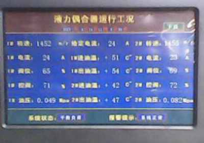
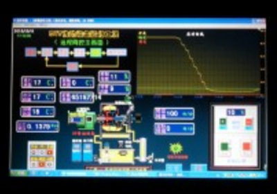
On-site Universal Box Touchscreen Display Interface Remote Computer Configuration Software Interface
• The innovative DYC electro-hydraulic flexible transmission and drive technology was introduced from Germany at the end of the last century. After nearly 20 years of absorption and transformation, it has evolved into a versatile technology applicable to the next-generation mechanical transmission and drive systems.
• Equipped with five major functions: Clutch, flexible coupling, soft start, stepless speed regulation, overload protection ;
• Capable of providing a one-stop solution to critical issues in mechanical transmission & drive systems: Overload soft start, dynamic load hazards, torque limitation, stepless speed regulation ;
• Compared to traditional mechanical transmission & drive technologies, it improves efficiency by more than 30% (reducing energy consumption, lowering costs, and minimizing emissions).
• It is a more straightforward, cost-effective, and user-friendly mechatronic integration technology.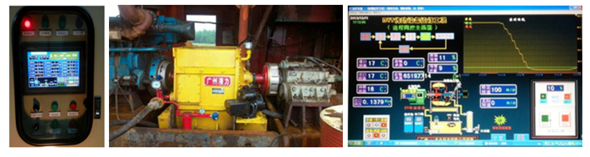
Has been successfully used for:
• Diesel-electro-hydraulic drive system for chain bucket dredgers (Soft start, stepless speed regulation)
• The drive system employs a diesel engine combined with DY electro-hydraulic power transmission and a gearbox (similar to the drive mechanism used in coal-carrying belt conveyors).
• The rotational speed is reduced from 1200 rpm to 4 rpm via a diesel engine, passing through Gearbox #1, a belt-pulley assembly, Gearbox #2, and finally a chain-driven bucket. This represents a typical hybrid mechanical drive system incorporating belt, chain, and gear transmissions. The bucket extracts sand at a frequency of 8–10 inches per cycle, resulting in high fluctuation density and significant impact in dynamic loads. Consequently, the alternating torsional vibrations generate extremely severe issues. However, the adoption of a novel electro-hydraulic drive technology has successfully addressed these challenges. Belt slippage, gear wear, spindle fracture, and black smoke from the diesel engine The issue demonstrates significant energy-saving effects.• Applications of Multi-Point Drive Control (Hongguo Coal Transfer and Loading Station, Liupanshui, Guizhou)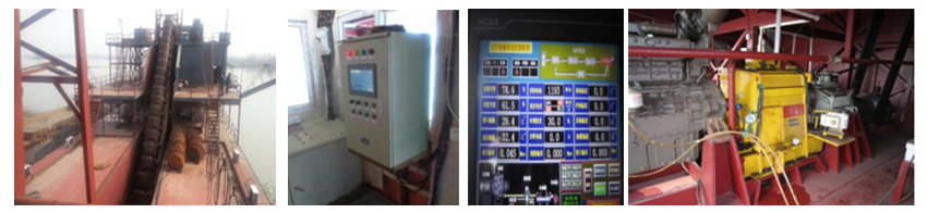
• 8 00kW × 2 Belt Conveyor DY Electro-Hydraulic Dual-Drive Intelligent Dynamic Control System
• Features: Soft start, multi-drive power balancing, stepless speed regulation, flexible coupling, clutch mechanism, and overload protection• High-power pump配套 (vertical pump, horizontal pump)
• Speed Control and Energy Saving System
• Laigang Wide and Thick Plate Plant
• 750 kW pump• Formosa Ha Tinh Steel Plant's 2,800 kW Dust Removal Fan (750 rpm)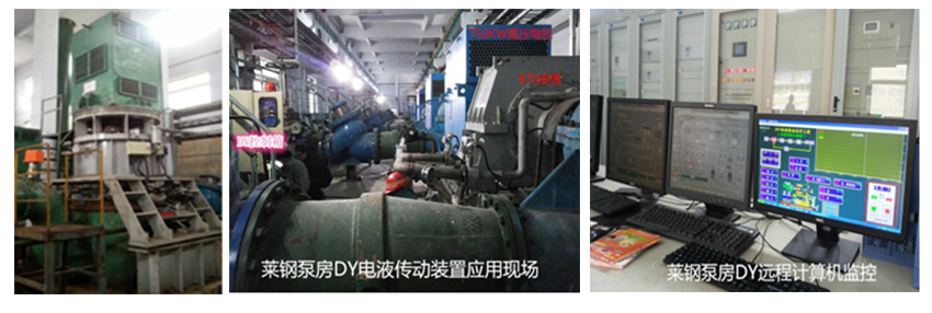
• Soft Start, Speed Control, and Energy-Saving System Unified• Can be used for tube mills, vertical mills, and rotary kilns.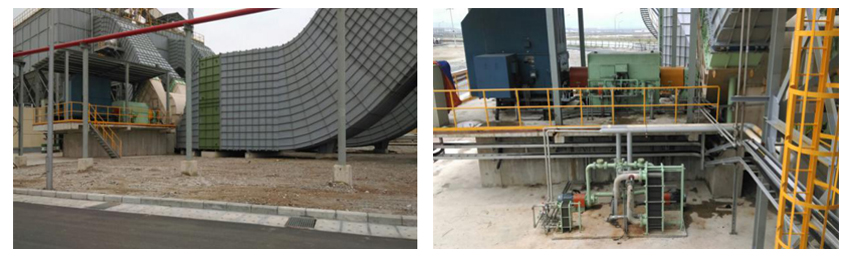
• Equipped with functions such as clutch operation, soft start, flexible coupling, stepless speed regulation, overload protection, and damping.• Widely applied across a diverse range of mechanical equipment...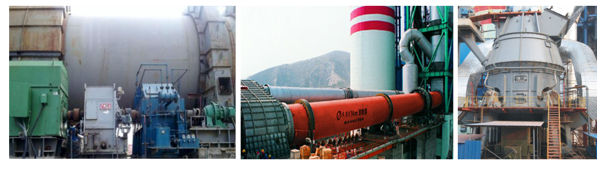
III. Upgraded Version of Computer-Controlled and Speed-Regulating Hydraulic Coupling (DYC, DY) – Electromechanical Integrated Drive Technology
Project/Product Hydrodynamic Speed Control Soft Start Variable-frequency speed control soft start 1. Performance 1. Adjust the fluid charge to achieve stepless speed regulation of the working mechanism.
2. Perform a soft start for the system, which can take an extended period of time without any limitations on the number of starts.
3. High overload capacity, capable of utilizing the motor's peak torque, with strong heavy-load starting capability.
4. Multi-machine drive enables power balancing and features automatic control of speed and current.1. Adjust the motor frequency for stepless speed control of the motor.
2. Perform a soft start for the system, which may take an extended period of time.
3. Poor overload capacity—increasing the overload factor requires upgrading the frequency converter to a higher level, which would add several hundred thousand yuan in cost per upgrade level.
4. Adjusting the motor frequency enables power balancing.2. Price Low investment Overall investment is high (requiring dedicated air-conditioned, ventilated, and dust-free electrical rooms as well). 3. Reliability High reliability
1. Even if the control system fails, the device can still be operated manually.
2. Simple structure, eliminating the need for a bypass system.Low reliability
1. If any component in the complex control system of the frequency converter fails, the system will become inoperable.
2. The structure is complex, and reliability decreases further in high-altitude areas. Although the electrical components used in current variable frequency drives have improved in reliability compared to earlier models, the large number of components—often numbering in the thousands—in a typical large-scale VFD significantly reduces overall system reliability. Therefore, for critical applications, it is essential to have either a speed-adjustable or fixed-speed bypass control system as a backup.4. Power Supply Fluctuation Voltage fluctuations do not affect the operation of the coupler. When the supply voltage drops below 80% of its rated value due to various reasons, the electronic inverter's built-in protection mechanism will automatically cut off the motor power supply. Even if the voltage drop lasts for just 100 microseconds, the protection system will activate immediately. The electronic inverter can be equipped with an automatic restart feature (which requires additional investment). 。
Even so, it takes at least 5 to 10 seconds for the motor to restart. During this period, the motor will come to a complete stop due to power failure, potentially causing significant disturbances to the process system and even triggering a safety shutdown of the plant. In smaller power supply systems, voltage dips are particularly prone to occur.
5. Harmonic Impact No harmonic interference Electronic variable-frequency drives generate higher-order harmonics of current and voltage in the power supply system. The magnitude of these harmonics depends on the size of the drive, the specific type of inverter used, as well as the short-circuit capacity of the power supply system. In systems with low power supply capability—particularly those characterized by smaller electrical capacities—the harmonic interference becomes especially pronounced. Such interference includes:
● Additional losses are generated in the motor and power supply transformer (therefore, the motor must be selected slightly larger, typically by about 12%).
● Motors and transformers generate additional noise (2–5 dB[A]).
● In addition to generating normal driving torque, the motor will produce pulse torque (these torsional vibrations will also be transmitted to the working machine, increasing mechanical impact and energy loss).
● Harmonic interference leads to additional energy consumption losses throughout the power supply system.
● Causes adverse effects on other electrical equipment and personnel, such as computers, controllers, etc.
● Harmonic issues may arise in capacitor banks, voltage transformers, ballasts, or capacitors within the power supply system, leading to increased energy consumption.
● May require the installation of harmonic filters to mitigate the effects of harmonics (which will incur additional investment and maintenance costs).6. Power Factor
Efficiency
High power factor with an efficiency of 97–98%.
Low power factor and low efficiency—typically ranging only from 90% to 94%—often mislead users regarding the true performance of variable frequency drives. First, accurately determining their efficiency through load testing is both challenging and extremely costly. Second, the additional losses caused by harmonics in motors, transformers, and the entire system are frequently overlooked. Lastly, the energy consumption associated with air conditioning cooling systems and harmonic filters is also typically not factored into the efficiency calculations.
Efficiency of the inverter at different speeds: (Siemens-produced Robicon Perfect Harmony series inverter)
Inverter efficiency %
Rotational Speed %
20
40
60
80
100
Torque %
20
74.6–85.9
84.9–94.8
89.2–94.2
91.5–95.3
92.8–96
40
84.5 to 91.0
91–95.5
93.2–96.1
94.8–96.6
95.6–96.9
60
88.3–92.5
93.2–95.7
95 to 96.4
95.9–96.8
96.3–97
80
93 to 90.3
94.3–95.7
95.7–96.4
96.2–96.9
96.6–96.8
100
91.4–93.2
94.8–96.7
95.9 to 95.7
96.4–96.5
96.5–96.6
7. Matching Motors
Standard squirrel-cage induction motor
It must use a dedicated variable-frequency motor, whose rated current is 8–10% higher than that of a standard induction motor, resulting in a 20% increase in temperature rise.
8. Voltage Transformation Requirements
Available high-pressure and low-pressure electric motors
If a low-voltage electronic frequency converter is used (since medium- and high-voltage converters are expensive and have lower reliability), a special step-down transformer must be employed, which inevitably leads to additional investment, increased floor space requirements, and higher maintenance demands. Alternatively, if a high-voltage motor is utilized—typically paired with a low-voltage frequency converter—a dedicated step-up transformer must be installed between the converter's output and the speed-controlled motor. This transformer must be rated for substantial capacity, as it needs to operate at frequencies below 50 Hz while preventing magnetic saturation during low-frequency startup.
9. Land Area
Smaller
The electrical switch room for high-power inverters requires significant space, leading to increased investment costs.
10. Electrical Cabinet Cooling System
No additional cooling required.
The heat loss generated within the inverter enclosure must be dissipated. This heat loss accounts for approximately 5% of the rated power, independent of the actual motor load and speed. For high-power inverters, this loss becomes particularly significant. The cooling air must be filtered through a dedicated cooling fan before being blown into the enclosure to maintain a cool operating environment. The maximum allowable temperature of the cooling air is 40°C, which necessitates substantial air circulation. As a result, the energy consumption associated with air conditioning and cooling fans often exceeds the inverter's own power losses.
Additionally, an air-to-water heat exchanger can also be used; however, this option involves high initial investment and significant maintenance costs.
11. Electrical Cabinet Noise
None
The inverter generates significant noise. Large-scale inverters produce noise levels exceeding 85 dB(A).
12. Equipment Maintenance
General Mechanical Maintenance
Troubleshooting and maintenance are highly time-consuming and costly; therefore, to resolve the issue, it is essential to consult with experts from the supplier.
13. Spare Parts
Affordable mechanical spare parts
A large number of spare parts are required, and only the manufacturer can supply them. However, due to the rapid advancements and changes in electronic technology, some components will become obsolete within just a few years, making it increasingly difficult to procure them.
14. Packaging and Transportation
Standard Equipment Packaging
The costs associated with factory testing, packaging, transportation, installation, and equipment startup are extremely high. Typically, these expenses are not factored into the comparison of equipment prices—nor are the costs for training maintenance personnel and organizing product documentation.
15. Additional Cables
No need.
If low-voltage motors are used in conjunction with low-voltage variable frequency drives, the connecting cables between the step-down transformer and the input terminals of the VFD, as well as those between the VFD output terminals and the speed-regulating motor, must be connected in parallel using multiple cables (e.g., four cables are required for a rated current of 1000 A). Additionally, these cables should be terminated in a dedicated junction box specifically designed for motor wiring. During motor maintenance, all such connections must be disconnected, a task that can be challenging due to the large diameter of the cables. Furthermore, the significant heat loss within these thick cables can substantially impact overall system efficiency.
16. Lubrication System
The hydraulic coupling is equipped with a lubrication system that provides lubricating oil to the bearings of both the motor and the working machine.
Large high-speed motors typically use sliding bearings instead of rolling bearings. Motor sliding bearings, as well as pump bearings, require regular maintenance. These sliding bearings must be supplied with oil for lubrication, necessitating the installation of a separate lubrication system—adding both additional costs and maintenance requirements.
17. Frequency Conversion Method
There is no such requirement.
There are essentially two types of inverters: voltage-source inverters and current-source inverters. Voltage-source inverters have lower efficiency and generate more higher-order harmonics compared to current-source inverters. If no motor is connected at the output end of a current-source inverter, the inverter will be running under no-load conditions. Under such circumstances, neither operation nor trial runs can be performed, nor can faults be tested or diagnosed, as these tasks cannot be carried out when the system is unloaded. If a motor is not available at that moment, or if the motor has not yet been prepared, or if operational constraints due to factory conditions prevent its activation, these limitations can lead to significant inconvenience.
18. Control System
Adopt a simple on-site control system. Equipped with on-site/remote/automatic/manual modes.
The frequency converter requires the arrangement of additional control and monitoring equipment in the switchgear room where the converter is installed. This means that extra cables, relays, internal interlocking systems, and starting circuit devices must be added to meet the control requirements, thereby increasing costs, failure rates, and maintenance workload.
19. Explosion-proof Requirements
Speed-regulating hydraulic couplings all come with underground safety certification.
Meeting explosion-proof requirements involves significant cost expenditures and is relatively difficult to achieve.
From the comparison above, it is evident that both hydraulic speed control soft starters and variable-frequency drive soft starters can achieve soft starting and multi-drive power balancing. However, as shown in the comparisons from point 2 to point 19, the use of a variable-frequency drive system is more complex, involves additional drawbacks, has a shorter service life, and incurs higher management and operational costs.
IV. Energy Efficiency Comparison Between Variable Frequency Soft Start and Hydraulic Soft Start
DY Electro-Hydraulic Energy-Saving Drive System, featuring a rated transmission efficiency of 97–98.5%, with no electromagnetic or electrostatic interference. It operates on standard power frequency and is designed to work seamlessly with asynchronous energy-saving motors, forming an ultra-high-efficiency drive system that delivers even greater energy savings. Variable-frequency speed control utilizes a variable-frequency motor, which, at rated operation, draws 8–10% higher current and experiences a temperature rise that is 20% greater compared to standard asynchronous motors. Additionally, the heat generated by the inverter itself amounts to 50–60 watts per 1 kVA of capacity, resulting in additional energy consumption when compared to using a power supply operating at line frequency. Additionally, to enhance the reliability and stability of inverter operation, extensive auxiliary peripheral electrical equipment must also be configured, including transformers, power circuit breakers, AC contactors, filters, reactors, braking resistors, and more. These electrical configurations collectively account for a power consumption exceeding 5%. It is evident that, compared to the DY electro-hydraulic energy-saving drive system, the variable-frequency drive system exhibits higher overall energy consumption and lower efficiency under rated operating conditions.
V. The DY electro-hydraulic drive unit also features excellent flexible transmission characteristics.
DY electro-hydraulic flexible transmission and drive technology not only delivers excellent drive control performance but also leverages the unique advantages of hydraulic flexible transmission. By optimizing the start-up and operational characteristics of working machinery, it effectively mitigates the hazards associated with dynamic loads (such as torsional vibration, resonance, and overload), thereby reducing operational maintenance costs. Additionally, this technology helps minimize configuration redundancy in transmission and drive systems, ultimately lowering overall investment expenses.
1. By altering the resonant speed of the shaft system, a larger torsional angle based on torque (indicating lower stiffness) results in smaller impact torque and a lower resonant speed. The torsional stiffness of the hydraulic coupling device is adjustable, allowing it to operate at an optimal torsional angle (slip) according to the varying load torque, thereby minimizing resonance.
2. Reduces torsional vibrations in the shaft system, making it particularly suitable for operating conditions with frequent load fluctuations. The hydraulic coupling device uses 30–40# turbine oil as the transmission medium, providing significant viscous damping (increasing frictional resistance). Capable of rapidly attenuating vibrations, converting the energy of torsional oscillations into heat, and dissipating it through thermal radiation. This will help reduce mechanical impact and wear in the transmission shaft system, enhancing reliability and extending service life.
3. When equipment operation is subjected to unexpected overloads, it often leads to damage of the transmission system or other mechanical components. If a hydraulic coupling device is employed in the drive shaft system, Leverage its clutch (semi-clutch) function By interrupting the transmission torque or limiting torque transfer, a safety protection function can be achieved.
4. The DY electro-hydraulic drive features a clutch function, enabling the motor and working machine to start independently. This clutch characteristic ensures that the motor can initiate operation either under no-load or heavy-load conditions—allowing for full-voltage starting of the motor. As a result, startup time is significantly reduced, and inrush current is minimized, eliminating the need to address the common issue of "using an oversized motor for light-duty applications." The motor starts first; once it reaches its rated speed, the hydraulic coupling is gradually engaged to smoothly load the working machine, achieving stepless speed control from 0% to 100%. Traditional variable-frequency control relies on conventional V/f control, where the voltage drop across the motor increases relatively as the motor speed decreases. This, in turn, leads to insufficient excitation, causing the motor to fail to generate adequate rotational torque. Under heavy-load conditions, it becomes necessary to equip the motor with a margin exceeding 1.5 times its rated capacity; otherwise, the motor may lack sufficient power during startup.
Through the comprehensive comparison outlined above, the new DYC electro-hydraulic speed-regulating soft-start device technology can replace the currently conventional variable-frequency and CST drives. It offers superior performance, requires lower equipment investment costs, achieves higher operational efficiency, and incurs lower running and maintenance expenses—making it the more suitable and advanced technology for industrial machinery transmission and drive systems.
Welcome to leave your information to get in touch with us!
Contact Information
Enterprise address: No.45 Hedi Road, Ducheng Town, Yunan County, Guangdong Province
Fixed line:0766 -7330991
E-mail:gdzxps@163.com
Website: http://www.gdzxpt.cn


Sweep to learn more
Copyright©2024 Guangdong Zhongxing Power Transmission Tech. Co.,Ltd.
